WIRING STANDARDS
By Matt De Maria
Have you ever wanted to quickly diagnose an electrical problem in your Porsche without going to the wiring diagram?
Have you ever changed an ignition switch or headlight switch and forgot to write down where the wires were connected?
Porsche in the 1950s standardized the wiring systems of their cars by adopting the German industrial standards. This was
the absolute standard up to 1983.
For instance, wires are generally color-coded for their function:
RED is for wires coming directly but unswitched from the battery.
BLACK is for wires coming from the ignition switch, and is used to describe wires that are able to deliver power that is controlled
by the on and off function of the ignition switch.
BROWN is used for wires that go to the ground on the car.
WHITE wires are used to go to the high beams of the headlights. Sometimes you will find a colored runner on one of the white
wires to differentiate between right and left.
YELLOW wires are used for the low beam circuit; a runner is sometimes also used here to differentiate between right and left.
GREY wires are used for the park light circuits (tail light,tag light, etc.)
BLACK runners are sometimes used for the left lights and RED runners for the right side.
BLUE is used for wires going to the indicator lights on the dashboard.
BLACK wires with colored runners are sometimes used for the turn signal functions.
WHITE runners are used for the left side and GREEN for the right side.
There is also a standardized code for the pin numbers on the electrical components (This is still used):
The number 30 or 30/51 next to a terminal indicates that battery voltage goes to this terminal.
The number 15/54 or 15 indicates that `keyed' battery power goes to this terminal.
The number 31 means that this point has to go to ground.
The number 50 indicates the power line from the ignition switch to the starter solenoid trigger terminal.
The numbers 53, 53a, and 53b are used for the windshield wiper motor.
The number 54 is used for the turn signal circuit.
The number 56 is used for the output of the headlight switch into the flasher switch.
The number 56a is used for the high beams, and 56b is used for the low beams.
The number 55 is used for the fog lights.
The number 58 is used for the park lights or running lights.
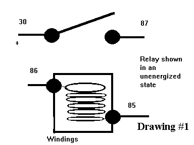
The number 85 is used for a ground point of a relay winding.
The number 86 is the power to the relay winding.
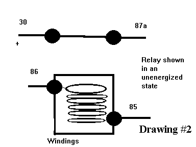
The number 87 is the normally open (static mode or unenergized mode) output of the relay.
The number 87a is the normally open contact for two switch relays.
A normally open relay is shown in Drawing #1, and a normally closed relay is shown in Drawing #2.
DRAWINGS #1
DRAWING #2
Now using the two codes together, we can verify the wires to an electrical item by the color and also verify the function of the electrical
item itself.
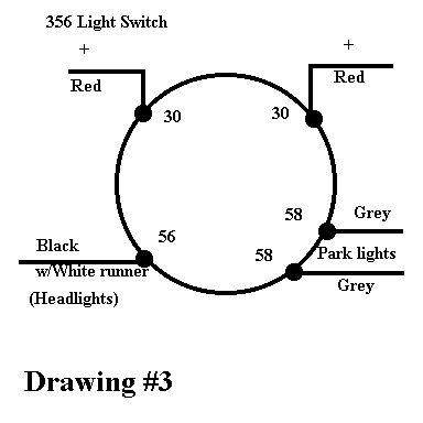
If we look at a 356A light switch, we have numbered terminals 30, 58, and 56. For wires, we have two red, two gray, and
one black with a white runner. From our standards we know that the wires are connected as drawn. See drawing #3.
DRAWING #3
From our standard code we also know that the two #30 terminals and red wires are hot (activates a test light) because red wires
or #30 go to the battery, the two #58 terminals and gray wires are hot in the two "on" switch positions because gray wires or #58
go to the park lights and the park lights work when the headlight switch is pulled into the first or second detent, and #56 and its wires
are hot in the second "on" position because this is the headlight detent position.
Again looking at a horn relay on the 356A we find in Drawing #4 the same codes prevail.
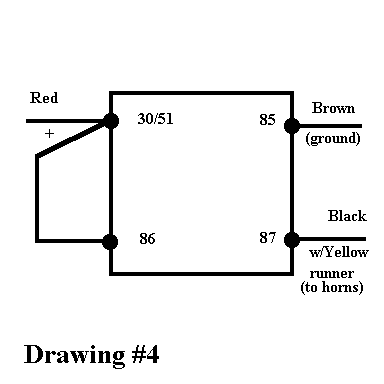
DRAWING #4
Reviewing our standard codes we know #30/51 and #86 are both hot terminals. Terminal #85 is the ground side of the coil in the
relay, and it becomes grounded when the horn button is activated as depicted in the factory wiring diagram. And finally #87 is the
output of the relay to the horns and becomes hot when the horn button is activated by grounding terminal #85.
In the 1974 911 wiring diagram, we will look at the headlight relay in the current tracks #4 and #5. See Drawing #5.
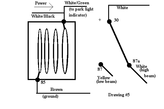
DRAWING #5
From our codes we know terminal #87a (the normally closed set of points) goes to the high beam circuit, and terminal #87 goes
to the low beam. Terminal 86 is hot when activated, and the white wire with the black runner feeds this terminal. The white wire
with the green runner goes to the park light indicator. Backtracking terminal #86 in the actual wiring diagram, we find it is hot when
the headlight switch is in the first detent, or the park light position. This means when the headlight flasher switch is energized, only
the low beams will flash. When the headlight switch is in the headlight mode, or the second position, terminal #86 is deactivated
and the relay returns to its neutral state. This means that activating the flasher switch will operate the high beam lights only in the
second position or the headlight position in the headlight switch.
In the wiring diagrams for the `85 Carrera we will look at B35 on the fourth wiring sheet. See Drawing #6.
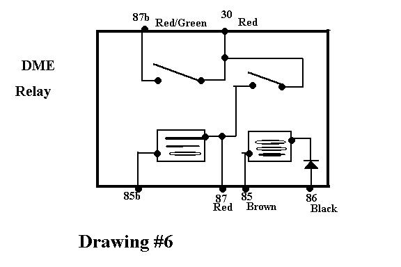
DRAWING #6
This relay's function can be understood with the help of the number codes and the color codes. This is a cascading relay or a
sequentially operating relay. Terminal #86 turns this relay on by a black wire, which is a "keyed" power wire. The power is
directed from terminal #30 to terminal #87, which also feeds power to one side of the injectors. Terminal #87 supplies power
to the second relay, and terminal #85b is the return to this second relay. Terminal #85b is a switched ground, which means it is
grounded through the ECU (the DME brain box). The ECU will ground #85b when it receives the signal inputs from the flywheel
sensors, signifying the engine is rotating. When the second relay is turned on, the power is directed to the fuel pump supplying fuel
to the engine.
In summary, knowing the color and number codes will greatly facilitate understanding the electrical system design, and thus lead to
an accurate diagnosis and quick repair of the electrical problem of your Porsche.