911 MECHANICAL FUEL INJECTION
From 1969 to 1973, Porsche built different versions of induction systems for the varied models delivered to the
American market. For the 911T, 1969 to 1971 models, Porsche used carburetors (Weber and Zenith-Solex). For all the
other models in this time period, Porsche used the Bosch mechanical fuel injection pump system. (See Picture #1)
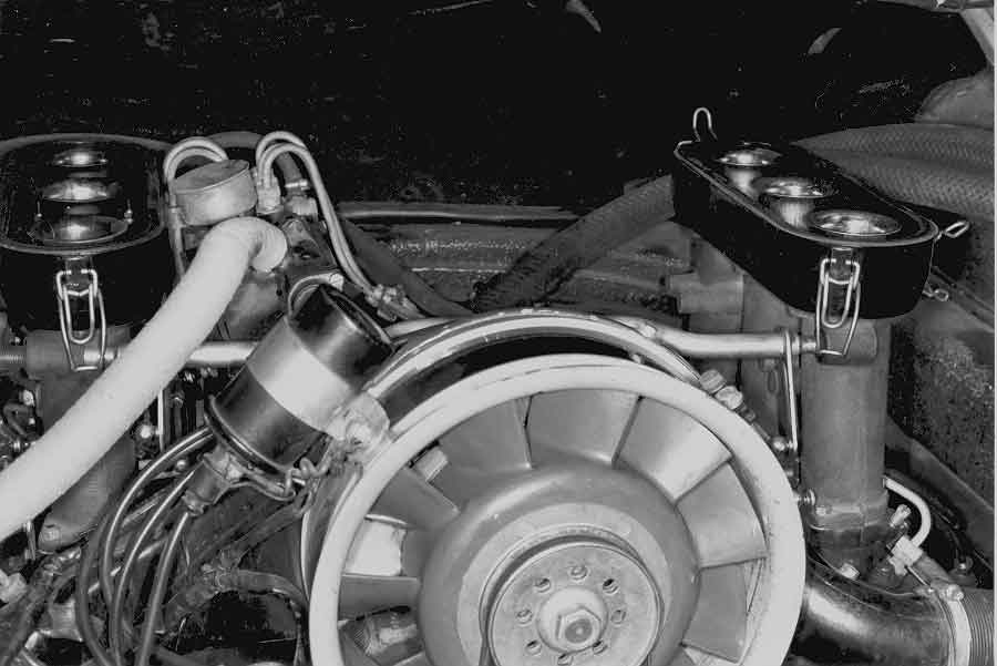
picture #1
The pump is called the Bosch PE pump (See Bosch Technical Instruction Book P/N VDT-UBP 210/1 EN). It is a
converted diesel timed fuel injection pump coupled with port injection. The advantage of this FI pump system over
carburetors was that this fuel injection system did not have the restricting venturi and venturi intensifier that the carburetors had.
Also where the carburetors had a distance of about 8 inches from the venturi (source of fuel) to the intake valve, the
distance from the port injector to the intake valve on the fuel injection system is about 2 1/2 inches. This port injection makes the
engine extremely responsive since the distance which the emulsified gas has to travel is greatly reduced, thus producing
more horsepower at (WOT) full throttle than the carburetor system could deliver.
But there were drawbacks with this system. All induction systems meter out fuel for the engine and fuel is usually metered
with respect to engine speed and load. Carburetors accomplish this by the Bernoulli effect of the venturi; the air passing
through the venturi creates a vacuum there and sucks gas out of the fuel bowl. It is obvious that the air rushing through the
venturi is basically proportional to the speed (RPM) of the engine; the throttle plate controls the load of the engine by
restricting the airflow and thus fuel also; if more horsepower is requested, the throttle plate is opened up more and the air
flow increases.
Consider two configurations of speed and load for carburetors. In one configuration, the engine speed is low and the throttle is WOT (low speed-high load) such as ascending a very steep hill in the bottom of a gear. In another situation, the engine speed is high and the throttle is almost closed (high speed-low load) such as lightly coasting down a hill on an interstate. Both these situations are likely to have the same airflow and thus the same fuel delivery quantity; since the fuel delivery is dependent on the airflow or the airmass flowing through the venturi. All in all, the carburetor is a very good compromise for accurate fuel metering and it produces very good driveability in many varying conditions.
However, the design of the fuel metering is different for the Bosch PE fuel injection system. As stated before, this pump is a timed mechanical pump. That means each injector will squirt fuel once every two revolutions or at the beginning of each cylinder's particular intake valve event. In order to accomplish six different fuel delivery events Bosch drove six metering plungers off of a small camshaft driven by the left engine camshaft. Fuel metering was accomplished by an internal piston in each plunger that rotated in one direction to deliver more fuel and rotated in the other direction to
deliver less fuel. All the pistons were controlled in unison by a toothed rack similar to a rack and pinion steering gear.
This toothed rack was controlled by a three dimensional space cam. An arm with a steel ball rested on this cam and all
movements were translated mechanically to the toothed rack. This cam changed contour with the speed of the FI camshaft
which is driven off of the engine camshaft, and thus was proportional to the speed of the engine. And this cam rotated its
contour in proportion to the throttle opening. The theory is that load is proportional to throttle opening. With the Bosch
system, the airflow is not measured directly at all; the fuel delivery is dependent on two mechanical algorithms, engine
speed and throttle opening.
With the carburetors, the fuel metering is performed in direct proportion to the actual airflow. With the Bosch system the
metering is related to both engine speed, which is a linear relationship, and to throttle opening, which is an estimate of
needed fuel quantities per degree-opening of throttle. Consequently the space cam was not an entirely accurate model of
fuel metering at part throttle conditions. Characteristically the fuel metering would go lean and the car would develop a
lean surge at light or part throttle.
Stating again, the Bosch PE system, does not directly monitor fuel with respect to air flow or air mass. From the increasing
demands for less emissions in the latter part of this time period (69-73), Porsche went to the Bosch CIS system [in 1973
1/2] whose fuel delivery was directly dependent on air flow. Even though the Bosch PE system is known for its response
and horsepower it is well known for its part throttle driveability surging.
This system would need retuning about every 6 months. It seems that the pump and stacks would have a usable life of
about 50K miles. On the pump the 3-dimensional cam is made of soft steel. The steel ball from the rack would wear a groove in the space cam. The ball jumping in and out of the groove would cause very large scale changes in the CO, which is the main
criterion for rebuilding the pump. The stacks are made of plastic and the throttle shafts wear out in the same mileage
period causing the idle speed to be inconsistent.
Setting up or tuning this pump is a laborious procedure. It is described in the Porsche publication #4532.20 (and
#4532.21) entitled "Mechanical Fuel Injection check,measure,adjust."
Basically this Porsche publication has a ten point checklist for setting up the Bosch pump:
1. Air cleaner element
2. Compression loss and leakdown
3. Spark plugs and connectors
4. Dwell (Points)
5. Ignition Timing
6. Fuel pressure and flow (information in section SF in the 911 Work Shop Manual VOL 1)
7. Injectors (no information in the manuals)
8. Injection timing
9. Correlation
10. CO test
a.part load
b. at idle
In addition to these items, if the car has an unknown service history or has had fuel delivery problems, these additional items need to be serviced:
A: an oil and filter change, especially if the oil is gas contaminated as this will affect the CO reading.
B: a valve adjustment, because a tight valve will cause a miss when the engine gets warm.
C: fuel filter for obvious reasons.
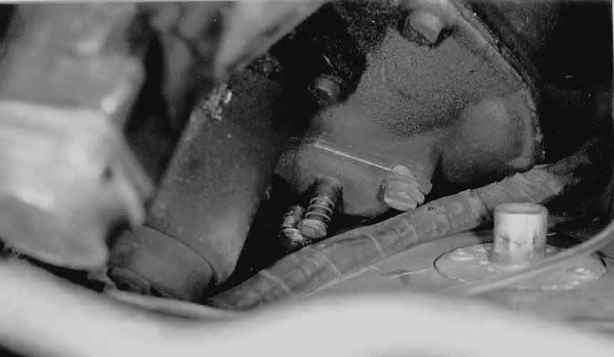
D: check hose from heaterbox to thermostat. And the left heaterbox must be in good condition in order to supply hot air
(122oF for the early 2.0L cars and 127oF for the late cars). (See Pictures #2 and #3.
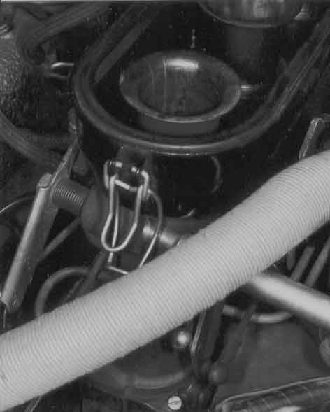
PICTURE #2
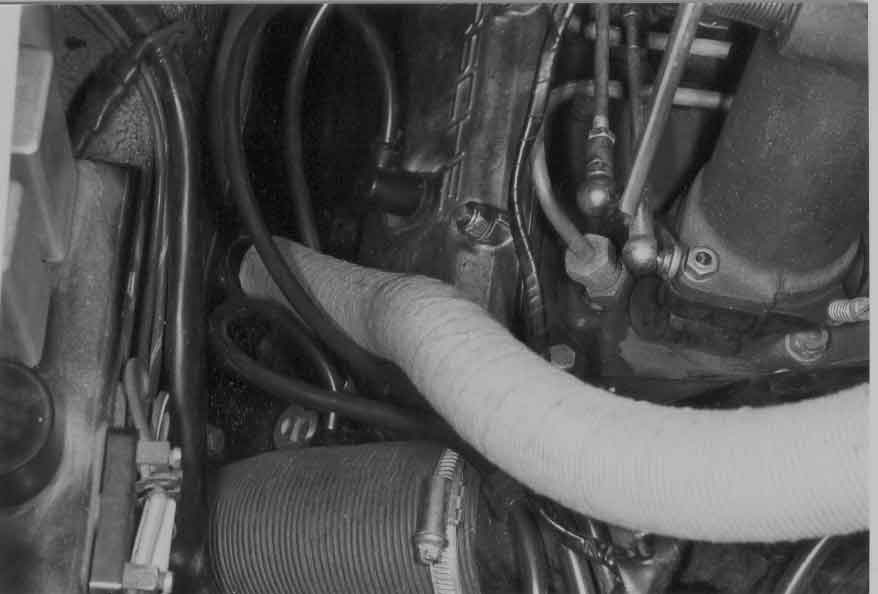
Picture #3
Also see Picture #4 for an example of a leaking hose.)
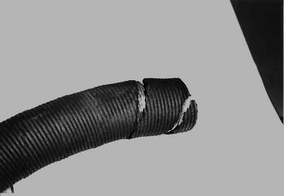
PICTURE #4
Reviewing the ten point list item by item we will note:
1. Air filter---self explanatory
2. The Leakdown should be less than 10%. Compression deviation should be less than 25 points.
3. Install new plugs. The old DPO plugs (Bosch) are particularly effective.
4. Dwell angle---self explanatory
5. Timing---self explanatory
6. Fuel pressure is measured at the return line to the fuel filter. The pump delivery should be 900-1000cc in 30 seconds;
the pressure should be 8.8psi-14.8psi.
7. The early injectors are disassemblable; but it is best to have them rebuilt professionally when needed. The easiest
method to measure the efficiency of the injectors is to analyze the spark patterns with an ignition analyzer. High KV's
indicate a clogged injector. Low KV's indicate an open injector. Check performance at idle and off idle.
8. Injection timing. The injection timing is particularly
important. The procedure to set up the timing is first to find TDC for #1 cylinder. This is found by simultaneous aligning
up the Z1 mark on the crankshaft pulley with the split in the crankcase halves and by having the rotor point to the #1 notch
in the rim of the distributor.
See Picture #5 where Z1 is the mark to the right of the alternator notch and the FE mark is to the left of this notch.
PICTURE #5
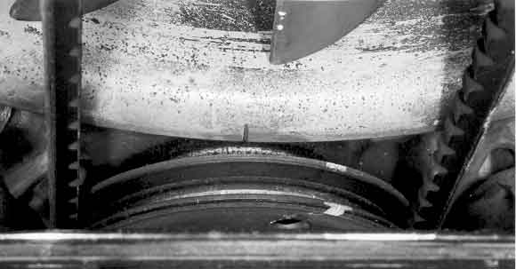
Now turn the crankshaft an additional 360o clockwise. The Z1 mark will still line up with the case. Now turn the crank
an additional 40o clockwise until the FE mark on the pulley aligns up with the crankcase centerline. This is the initiation
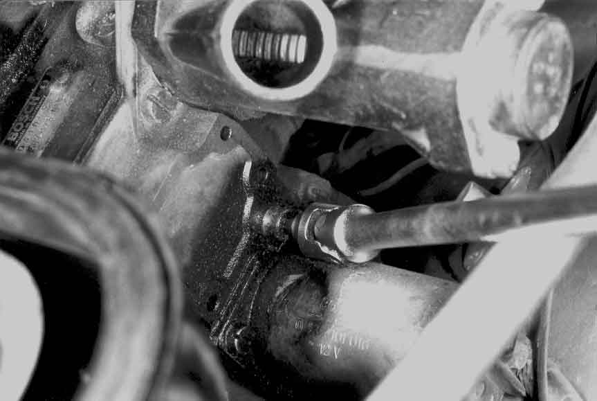
point of the intake valve opening on the reverse overlap. Now at this point on the backside of the fuel pump there is a line
on the pump gear hub which should line up with a corresponding line on the pump housing.
(See Picture #6 for a view of the rotor pointed away from the notch on the distributor rim while the crankshaft pulley is
at the FE mark.)
PICTURE #6
See Picture #7 for a view of the pump timing marks. Be sure to check the tension of the belt as this will affect the
alignment of these two timing marks.
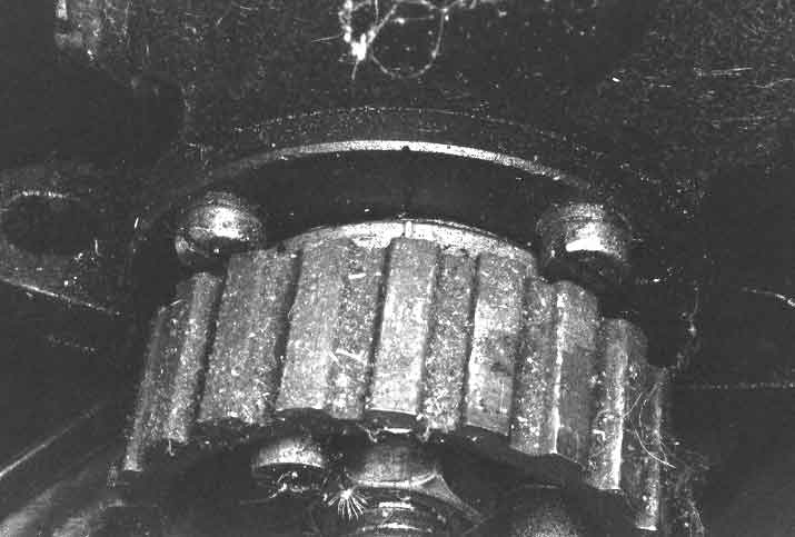
PICTURE #7
9. Correlation. The correlation check is done to ensure thatthe stack throttle plates are synchronized correctly to the pump
throttle lever in order to guarantee that the fuel is metered the correct amount to the throttle opening. This is accomplished
by installing magnetic protractors on the pump lever and the left (#1 cylinder) and right (#4 cylinder) throttle levers.
(See Picture #8 for a view of the protractors with needles.)
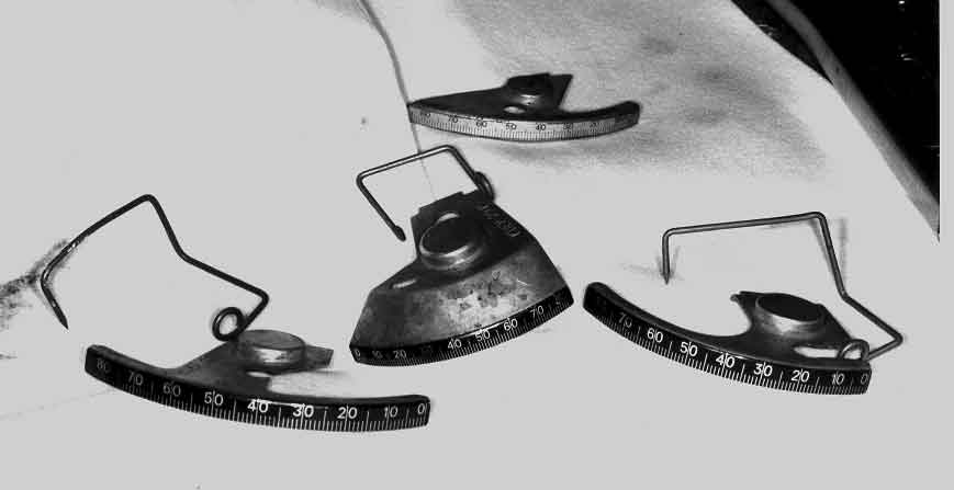
PICTURE #8
Make sure the protractors do not hit the shrouding. Install pointers accordingly. Make sure that at the idle position that
all linkages are resting on their stops.
(See Picture #9, #10, and #11 for views of the protractors and needles on the left stack, right stack, and on the
pump.)
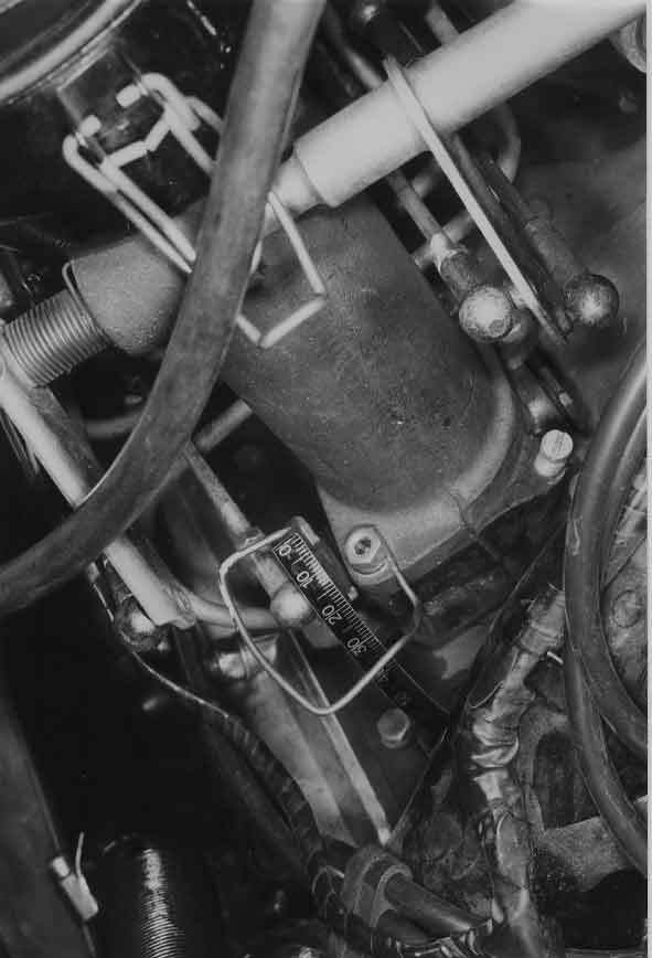
PICTURE #8
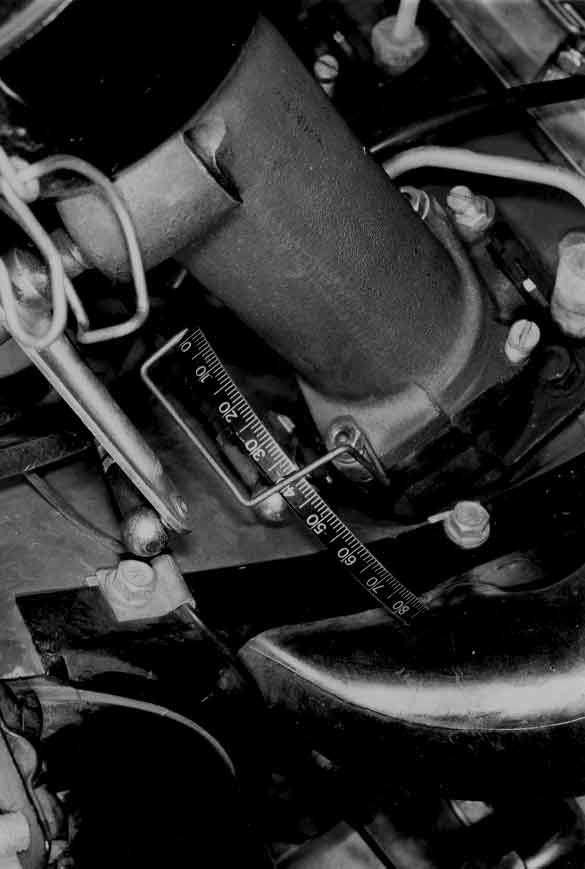
PICTURE #8
Picture #10
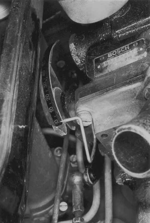
PICTURE #11
Gently open the pump lever by the increments listed in the Porsche publication and check to see if the throttle plates are
opened at their specified amount also listed in the publication (correlation). If there is a deviation from the specs,
measure the length of the actuating rods (114mm +/- .2mm). First check the rod from the pump to the cross shaft to see
that it is the correct length (mentioned above). Next check the left and right rods. Ideally their lengths should be 114mm.
The difference between the two lengths should be no more than 5mm. If the difference is greater, adjust by loosening the
nut on the left side of the cross shaft and moving the left lever with respect to the right lever and retighten. After this work
is performed check the microswitch adjustment mentioned in the publications. If the microswitch is an aftermarket
replacement, the travel is not as much as the OEM style ( about 1/2 a turn).
(See Picture #12 for a view of an aftermarket switch) Check to see that the button is depressed enough to turn on the
switch but not enough to hold the throttle off of its stop.
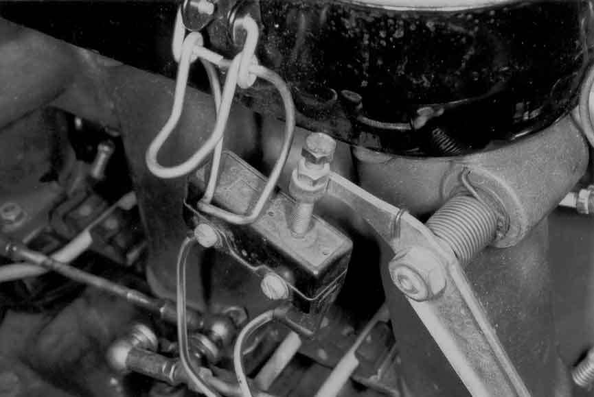
PICTURE #12
Also from the 69-71 "Technical Specifications" book the throttle valve push rods are 149.5 +/- 1mm and the pull rod
from the accelerator linkage bellcrank to cross shaft is 275mm.
10. CO SETUP. The first step is to synchronize the throttlestacks. This is done to ensure an accurate measurement of
the CO value at idle. A UNI-SYN can be used to perform this task also. If the throttle shafts are worn, in some cases the
throttle stops have to be readjusted to equalize the airflow through all of the stacks.
PICTURE #13
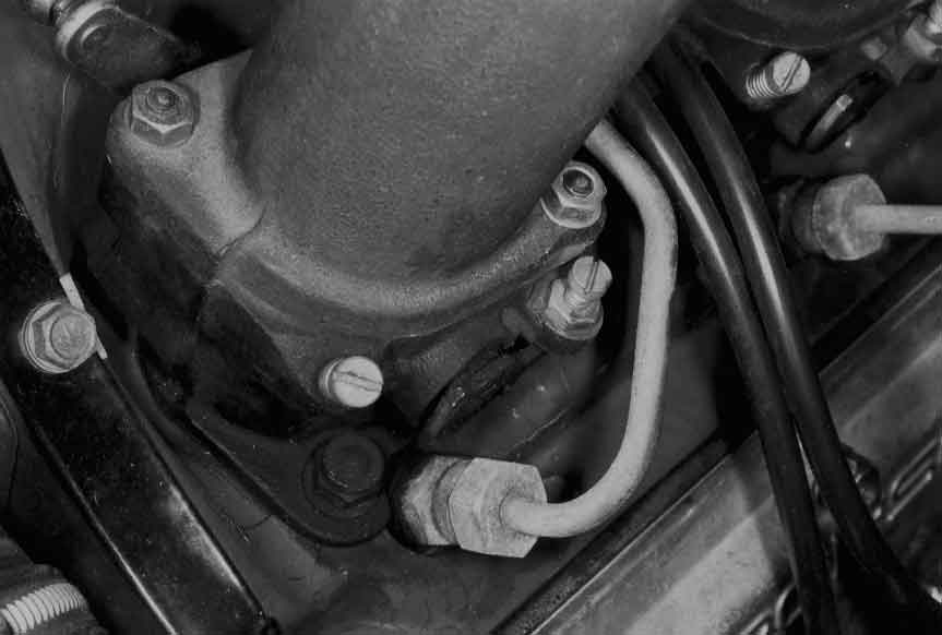
See Picture #13 for a view of the idle speed screw next to the manifold nut and the throttle stop screw with the
jamnut.) Be careful not to go overboard as this adjustment affects the idle speed and the mixture. For the CO setup
follow the literature closely. The part load adjustment must be done first; and then the idle CO setup is performed.
(Remember the idle system is similar to the dependent idle system in the WEBERS; any change in the main jets affects
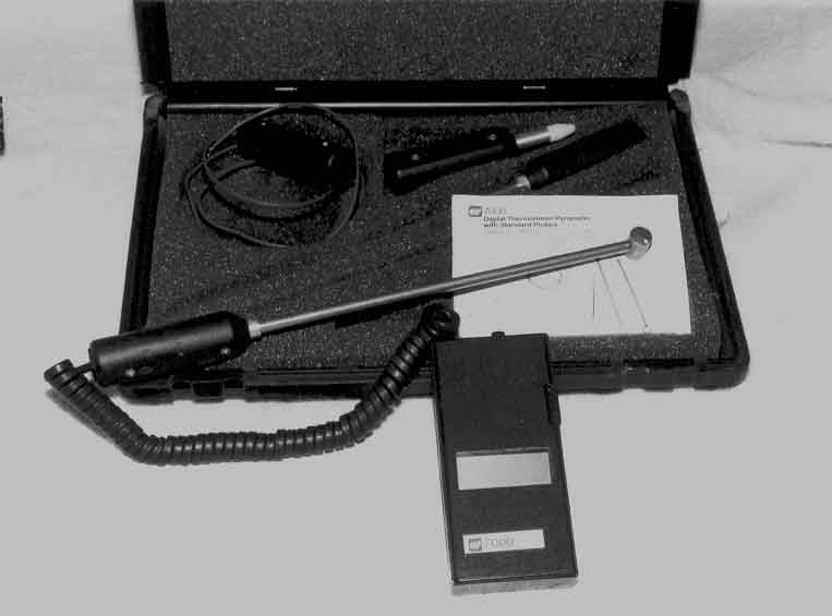
the idle mixtures.) Next consult the chart for the part throttle setup on page 25 of the Porsche publication mentioned
earlier. For the 2.0 liters and the 2.2 liters, instead of using P237 to measure intake air temperature, the TIF set P/N
7000 Digital Thermometer with its air probe (see Picture # 14) can be used.
PICTURE #14
The throttle angle opening is measured with a protractor off of the left stack for the 2.0 and the 2.2 liters. For the 2.4
and 2.7 liters the right stack is used. It is easiest to perform this part throttle measurement with the car on a lift with the
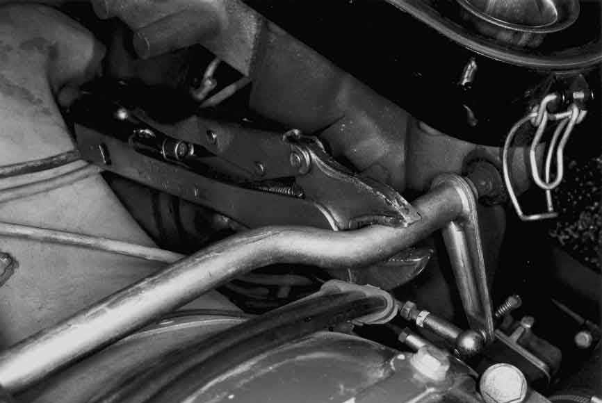
wheels clear on any obstacles. Set the throttle angle to the appropriate value (Use vice grips on the right side of the
cross shaft to lock this setting.
Picture #15
See Picture # 15) With the engine warm (oil temperature 175oF or more) shift the car into second gear and let the
clutch out with the vehicle in the air. Gently and quickly apply the footbrake until the desired RPM is attained for
about 20 to 30 seconds. (The CO should stabilize its value in about 5 seconds.) Record the value.
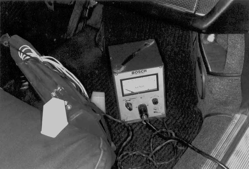
For CO measuring equipment use either the early Bosch CO analyzers
PICTURE #16
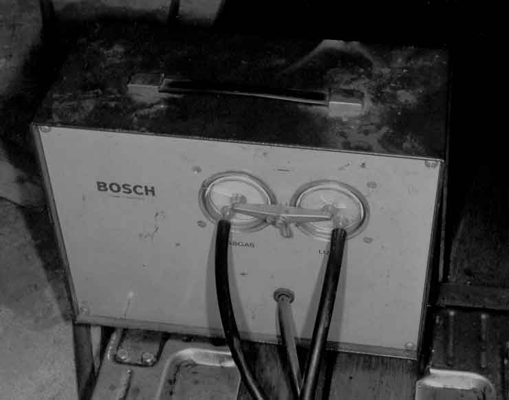
PICTURE #17
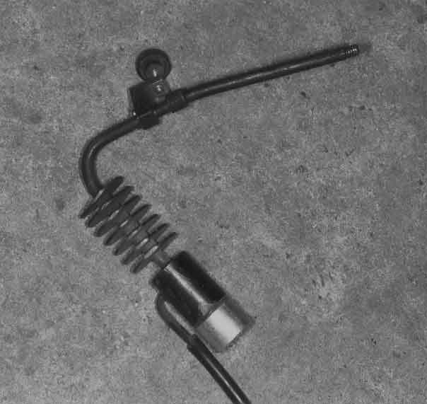
PICTURE #18
See Pictures #16, #17, #18 for a look at the early Bosch control unit powered by a battery pack, the early Bosch gas
bench with the test gas filter and the ambient air filter, and the gas pickup fixture that fits into the tailpipe.) or one of
the three late 4 or 5 gas analyzers (MPSI, John Beam, or Vetronics) that are true in-flight measuring units.
(See Picture #19 of an MPSI)
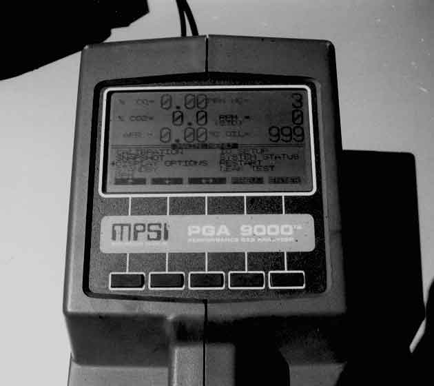
PICTURE #19
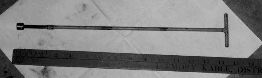
For adjustment of the part throttle, shut down the engine and remove the 5mm allen screw (with the tool in Picture #20
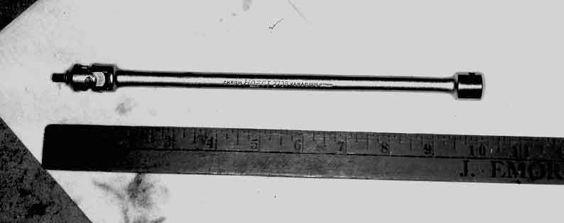
PICTURE #20
covering the rack adjustment screw shown in Picture #21. For the 2.0 liter cars back out 14mm wrench size bolt
under pump lever shown on page 29. Turn rack adjustment screw in the appropriate direction also listed on page 29.
A locally made screwdriver is used that has a body diameter of 3/8" shown in Picture #22.
PICTURE #21
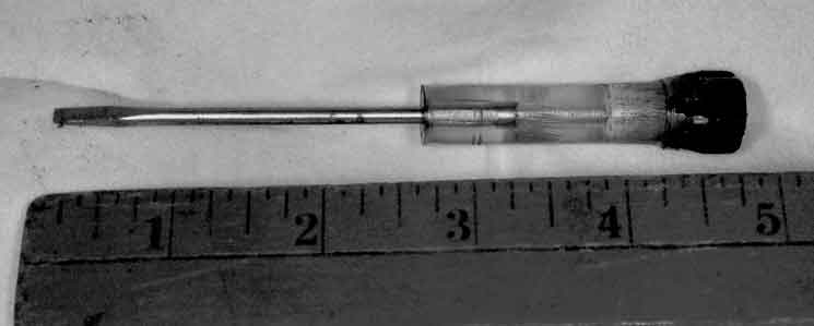
PICTURE #22
As stated in the Porsche publication, check the CO after every 2 clicks of the screw. Check the chart for the correct
value desired. Reinstall screw for the 2.0 liters.
For the idle CO setup make sure the idle is 900 +/- 50 RPM. Measure CO while engine is warm and idling. If
adjustment is needed, shut engine down and adjust idle CO screw (Picture #23) with tool P230b (Picture #24)
PICTURE #23
PICTURE #24
in the appropriate direction listed on page 33. Restart engine, reset idle speed, and recheck CO.
In order not to spend too much time on repair diagnostics that would make this article too long, a few salient points
should be mentioned:
1. If the CO is too rich and won't decrease, check to see if the warmup thermostat is clogged up with dried grease from
the heaterbox heater line.
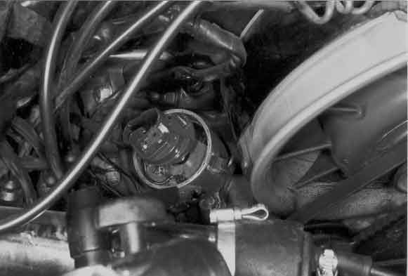
2. If the car is hard to start, check the thermo-time switches for function and check the enrichment solenoid on the early fuel
injection units. The 2.2 liter cars and later had the thermo-time switch operate a solenoid on top of the fuel filter. When
triggered the solenoid would feed gas to a fuel rail above each set of stacks. Each rail would have a set of three holes that
squirted gas into each stack. Needless to say on a cold engine that would pop and snort this arrangement was a source for
many fires. In this instance it was wiser to suffer a longer cranking time than to risk a fire.
3. If there is a problem with backfiring, first check the microswitch for function. Then check the shut-off solenoid with a test
lamp just by revving up the engine and letting it idle. The lamp should light on deceleration and go out at idle. If this happens
check the solenoid. If this does not happen check the RPM relay.
In summary the Bosch PE fuel injection is a fuel delivery system designed for high horsepower engines
with the emphasis on the high RPM horsepower rather than low end torque and driveability. It is a laborious system to set up
and expensive to rebuild. In the early 80's when the owner of a car with a worn out PE pump faced a rebuild, the choice of
rebuilding and setting up the pump system was weighed against the cost of purchasing a good used set of Weber carburetors
which were plentiful and cheap because of all the 911's from the 60's that had rusted away. Nowadays good used Webers are
impossible to find with good throttle shafts. New Webers are impossible to find and/or they are extremely expensive. Nowadays
the decision to keep the PE pump or to switch to carburetors is a very difficult decision.
As a postscript, the intent of the CMA book is to ensure the health of the engine before the setup of the pump. Since the fuel is
metered in relation to throttle opening and RPM, an unhealthy engine will draw less airflow and thus not meet the calibration.
of the space cam. Similarly if the compression (piston type) , cams, port openings, throttle stack diameter, exhaust system, even
pump type is changed the airflow is changed and will not match the space cam. The performance will be untunable without modifying
the space cam which is very difficult.
Also with the escalating values of the MFI cars today converting to carburettors is now not a preferable solution.