944 CLUTCH HYDRAULICS
By MATT DE MARIA
The 944's clutch is operated hydraulically. The clutch pedal actuates a clutch master cylinder, similar to a brake master cylinder. The pressure produced is transmitted through a flexible hydraulic hose (to allow for movement) to a clutch slave cylinder mounted on the engine bell housing. The clutch slave cylinder exerts pressure against a pivoting lever which pulls the throwout bearing of the pressure plate to disengage the clutch disc.
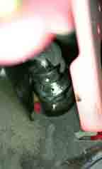
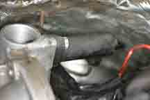
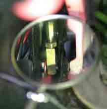
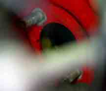
One of the failure modes of a hydraulic system is fluid leaks. Fluid can leak either at the slave cylinder, the hydraulic line, or the clutch master cylinder. In Picture #1 brake fluid is leaking through the protective boot of the clutch master cylinder on the inside of the firewall.
PICTURE #1
In this particular case, because of the mileage, it was decided to replace all the clutch hydraulics.
Disassembly
To make the job less messy, a Vacula tool is used to suck all the brake fluid out of the clutch system. See Picture #2
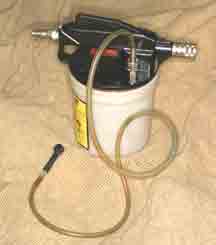
PICTURE #2
The Vacula tool is connected to the bleed valve of the clutch slave cylinder. (See Picture #3 where this is viewed from under the car.
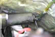
PICTURE #3
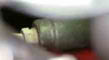
The bleed valve is opened with the 7mm wrench and the Vacula is turned on. The brake fluid will be sucked out of the clutch slave cylinder, the line, the clutch master, and finally out of the clutch reservoir. See Picture #4 for a view of the fluid level in the reservoir after it has been emptied.
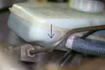
PICTURE #4
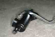
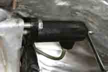
Next the clutch slave cylinder is removed. See Picture #5.
PICTURE #5
It is removed by unfastening the two 8mm bolts and the 12mm (ATF) tube nut on the metal hydraulic line. An “S” wrench makes the removal of the upper 8mm bolt easy. See Picture #6.
PICTURE #6
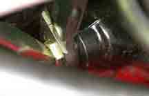
The flexible line is removed next using both a 19mm and a 12mm line wrench. See Picture #7 for a view of this connection under the plenum.
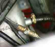
PICTURE #7
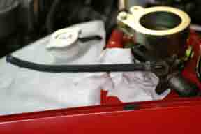
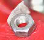
The other side of this line connects to the clutch master cylinder. See Picture #8. This is a 12mm (ATF) tube nut.
PICTURE #8
After this line is removed, the connecting pushrod to the clutch master must be disconnected from the clutch pedal linkage. (This requires that you be on your back underneath the dash) See Picture #9 for a view of the pushrod and the clip that must be removed.
PICTURE #9
See Picture #10 for a view of the pushrod.
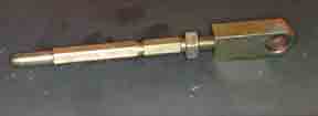
PICTURE #10
And see Picture #11 for a view of the clip and washer.
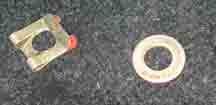
PICTURE #11
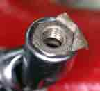
After removing the pushrod, the clutch master cylinder can finally be removed by unfastening the two 8mm nuts holding it to the firewall. Picture #12 shows the removed clutch master cylinder. And Picture #13 shows the mounting hole in the firewall.
PICTURE #12
PICTURE #13
ASSEMBLY:
Insert the pushrod into the new boot of the new clutch master cylinder and fit the unit onto the two 8mm studs on the firewall. Using a pair of long needlenose pliers install washers onto the two studs. Getting the nuts started onto the studs is a normally difficult procedure; but the operation can be made easier by putting a bit of masking tape onto the nut. See Picture #14.
PICTURE #14
And then insert nut and tape into a 13mm swivel socket. See Picture #15.
PICTURE #15
DO NOT TIGHTEN THESE TWO NUTS YET. Start the tube nut of the new flexible line onto the end of the new clutch master cylinder. See Picture #16. Wiggle the clutch master while starting the tube nut.
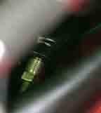
PICTURE #16
Once the tube nut is started on a few threads, a special ratcheting hydraulic box wrench is used to drive the nut home. See Picture #17 for a look at the tool.
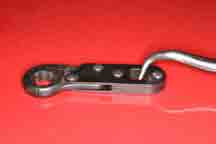
PICTURE #17
Picture #18 shows the tool in action also using a large screwdriver to add a turning tension for the ratchet to work.
PICTURE #18
After the tube nut is tightened, finish torquing the two 8mm nuts onto the studs on the firewall. Reattach the pushrod to the clutch pedal linkage; adjust the pushrod length to achieve the 1mm freeplay to the clutch master cylinder.
Reattach the flex line to the solid line underneath the plenum.
Attach the new clutch slave cylinder to the bell housing. For the present leave the two 8mm bolts loose so that the slave cylinder is about 8mm away from the face of the bell housing.
See Picture #19
PICTURE #19
Using a pressure bleeder (Motive, etc), bleed the clutch system. Check the clutch pedal play especially at the top of the pedal travel. If the pedal does not return the last 25mm of travel to the rest position, continued bleeding should be performed. This time with the pressure bleeder attached, push the slave cylinder toward the bell housing a few times to create fluid turbulence internally to evacuate any remaining air bubbles in the system. Finish tightening the slave cylinder.
In summary, the replacement of the clutch hydraulic system is not rocket science; it does require some procedures to make the job less messy, like draining the brake fluid from the system. And some of the work is unavoidable and uncomfortable, like getting underneath the dash to disconnect and reconnect the clutch master clip. But overall it is a doable project for most DIY afficionados.