By Matt De Maria
This article was previously published in PCA Potomac's
'Der Vorganger'
The 928's are known for their peculiar electrical problems. In particular the early 928's (1978-1986 US) are famous for their alternator charging problems. One common symptom that these early 928's would exhibit was that the alternator would not start charging until the engine was revved to about 3000 RPM at the time of the initial startup. The symptom would repeat at each startup and then the system would charge normally.
If the dashboard lights are examined during the daylight hours or in a brightly light environment, "red lighted boxes" are noticed at the end of the individual gauge movements when the ignition key is turned "on". These red backlit boxes signify a critical situation for each gauge they are associated with. The red backlit box on the voltmeter gauge should light (It is critical) when the ignition key is in the "on" position. It is placed at the lower end of the volt scale below the number 10
If the light does not energize, this circuit must be examined. If the wiring diagrams for the early 928's are checked, it is noted that current comes from the "keyed" power terminal (15) of the
ignition switch, goes through the indicator light, goes through the Central Electrical Board, goes through Terminal #14, Pin #1 (by the battery post in the engine compartment) and finally
terminates at the regulator of the alternator See Drawing *1.
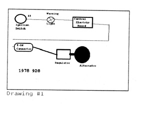
The purpose of that circuitry is to deliver power from the ignition switch to the voltage regulator of the alternator which is at a state of rest when the engine is started. If the engine is stopped it is not producing any current nor any voltage. Hence, current travels from the ignition switch through the light and terminates at the regulator. There is enough current draw to turn on the light. Since there is now voltage and current being delivered to the regulator of the alternator which is now turning (from the engine being started), the regulator delivers enough current to the moving rotor which in turn produces a magnetic field that the fixed field coils (stator) cut and thus induces current in the stator windings. There a three stator windings (3 phase). Each winding is fed into pairs of diodes to rectify the current into one direction. This rectified current and voltage is fed to battery. Additionally there is another set of rectifiers off of the stator outputs to feed voltage back to the regulator in order to tell it how much current to feed the rotor so as not to overcharge nor undercharge the system. As indicated in Drawing #2,
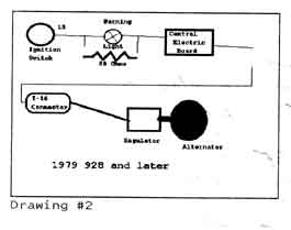
A change was made in 1979 where Porsche added
A 68 ohm resistor was added across the indicator light. This was probably added to deliver a little more current to the regulator in order to turn it on quicker. The most common problem in these early 928 circuits, was the indicator light burning out.
Somewhere between 1984 and 1986 Porsche superceeded the indicator light bulb to P/N 928 641 958 00. The glass portion of the bulb is physically bigger than the previous bulb. The plastic
reflector had been changed from black to white This bulb burned brighter than its earlier counterpart.
DIAGNOSTICS TO CONFIRM BURNED LIGHT
Check the wiring diagrams for the particular year 928 as the pin numbers vary. In drawings *1 and #2 the flow of current travels from the light where it loops in and out of the Central Electric Board and from there travels to pin #1 of the 14 Pin connector on the right hand side of the engine compartment. The first place to check is at the input pin at the Central Electric Board. With a digital voltmeter, the voltage measured should be battery voltage with the key "on".
******* If there is no battery voltage at this point, check at the output pin of the correct plug behind the dash cluster when the key is "on". (This is the wire that goes to the Central Electric
Board) Remember the plugs for the early 928s are not marked. Verify the correct plug and pin by correlating the color codes of the wires with the pin numbers in the wiring diagrams for the year in question.
*************If there is voltage at this point, the problem is between this pin and the Central Electric Board input pin.
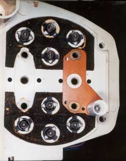
*************If there is no voltage at this point, check on the backside of the white plastic gauge plate on both sides of the bypass resistor shown in Picture #8
There should be no voltage at both ends of the bypass resistor. (If there is no voltage check backwards on the board for the "keyed power" voltage supply.) Lift one of the ends of the resistor and reinstall the machine screw. If the bulb is blown, one side will show voltage and the other side will not.
*****If there is battery voltage at this point on the Central Electric Board, verify the output pin voltage on the board. (There have been many cases where the connecting wires have broken on the backside of the Central Electric Board. Repair is tedious.) If there is voltage on the output pin of Central Electric Board, check Pin #1 on Connector T-14 This connector has been the source of problems also due to moisture corrosion on the pins.
The intent of this article is to show the procedure of replacement of this light bulb. There are some shortcuts not shown here because of the delicacy and complexity; the standard conservative approach is itemized.
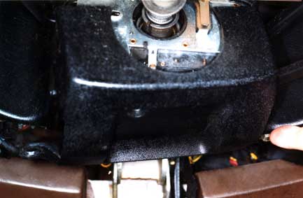
First remove the steering wheel, Next remove the long trim plate shown in Picture #1
Picture #1
Remove the plastic trim panel under the turn signal switch that is fastened with a chrome sheet metal screw shown in Picture #2 and with two 6mm bolts shown in Picture #3.
Picture #2
Picture #3
Next remove the two 6mm allen bolts (with 5mm allen wrench size). The right hand one is shown in Picture #4
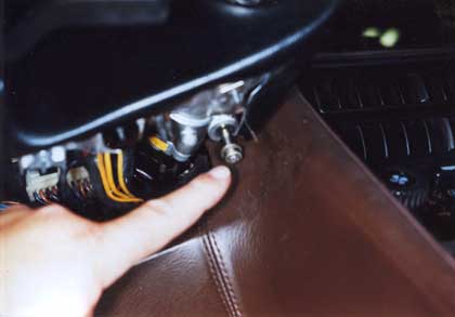
Picture #4
Remove the turn signal switch by loosening the 5mm bolt in its clamp on the steering column housing and unplug the white plastic plugs on the back of the switch. Gently wiggle the switch off of the steering mast while the dash nacelle is being lifted slightly at the same time. See Picture #5 for a view of the turn signal switch removed.
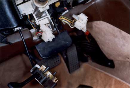
Picture #5
Now lift up the dash nacelle slightly and slide the entire plastic housing to the left about 1 1/2" simultaneously moving the left side of the housing to the front of the car about 1". The purpose is to clear the bracket on the right side of the nacelle that is shown in Picture #6
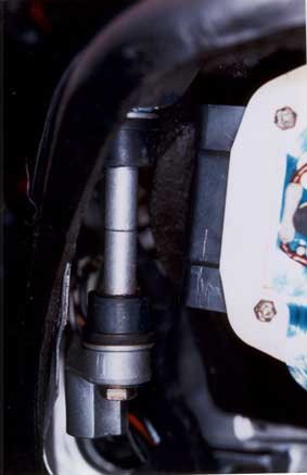
Picture #6
Once the gauge cluster is clear of the nacelle, unplug the three white plastic connectors from the cluster carefully by moving their locking arms in the appropriate direction. Mark the connectors as to where they go because they are all physically identical. Move the gauge housing to a clean area and place it face down on a soft surface. See Picture #7
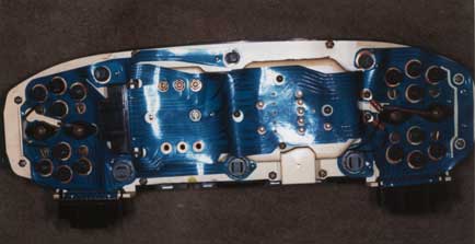
Picture #7
Remove the peripheral screws Do not remove the white gauge plate yet. Look at Picture #8;
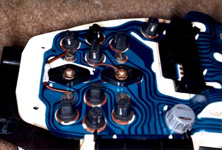
Picture #8
Remove the four slotted screws and the two 5mm nuts and the black plastic pieces See Picture# 9
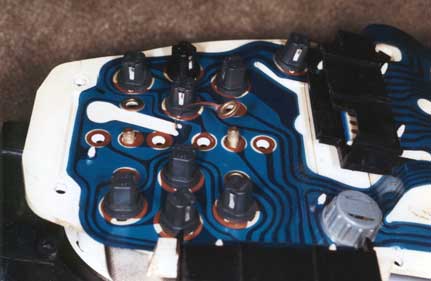
Picture #9
Remove now the white gauge plate from the black plastic housing; and place it back down on a soft surface to prevent scratching. Gently remove the voltmeter and oil pressure gauge cluster from the plate. The old ammeter light is shown in Picture # 10
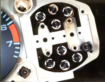
Picture #10
Remove the old light and replace with the new design light shown in Picture #11.
Picture #11
Reassemble voltmeter and oil pressure gauge head onto the white plastic gauge plate. [An additional operation should be performed at this time. The voltmeter is nonlinear in calibration. There is a calibration screw underneath the voltmeter face plate, It is probably most helpful to calibrate one point on the voltmeter. The number "12.5" is the most helpful number as
it is the usual value seen after the car has been started up and run for a few minutes. With a digital voltmeter attached to the battery post in the engine compartment, very carefully hook up the white gauge plate to the dash by the three connectors and run the engine (make sure all accessories are turned off in this procedure!) until the value of 12.5 volts is read on the digital
voltmeter. With a jewelers screwdriver carefully adjust the calibration so that 12.5 volts also is displayed on the dash's voltmeter. When this procedure is being performed take care to not bend the gauge needles.]
Assemble the white gauge plate into the black housing and continue on with the reassembly of the dash. As shown in Picture #12 the light is not functioning. And in Picture #13 the
new light has been installed.
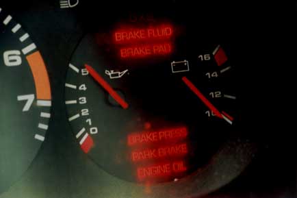
Picture #12
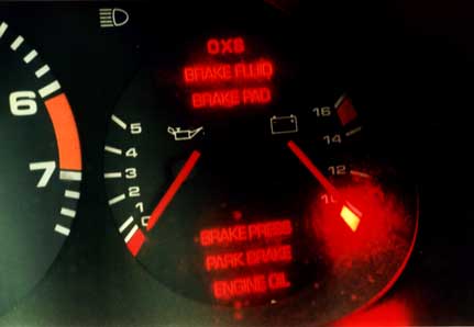
Picture #13
Note the brightness in comparison to the light on the oil pressure gauge.
In summary, 928 wiring problems are involved but not insurmountable. With the wiring diagrams and a clear logical procedure, any problem can be resolved.