911 STRUTS
The advent of the 911 marked a new era for Porsche in front end design in 1964. While the 356 had a heavy beam design,
the 911 had the "new" Macpherson strut design, which was light in weight and cheap to produce. In addition to having a
higher roll center than the beam front end, the Macpherson strut allowed uncluttered space between the strut housings and
lent itself easily to a steering rack design which gave a more positive feel to the steering response. The increased space
available allowed a large trunk for rear engined cars and plenty of space for a V-8 engine in a front engine car.
The 911 strut uses the same wheel bearing design as the 356C, its predecessor. In fact it uses the same wheel bearings as
in the 356C which has much less weight on the front end. This design continued on both the 911 and 930 up through 1988
where the front end weight increased 300 pounds or more over the 356.
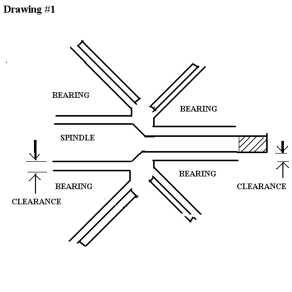
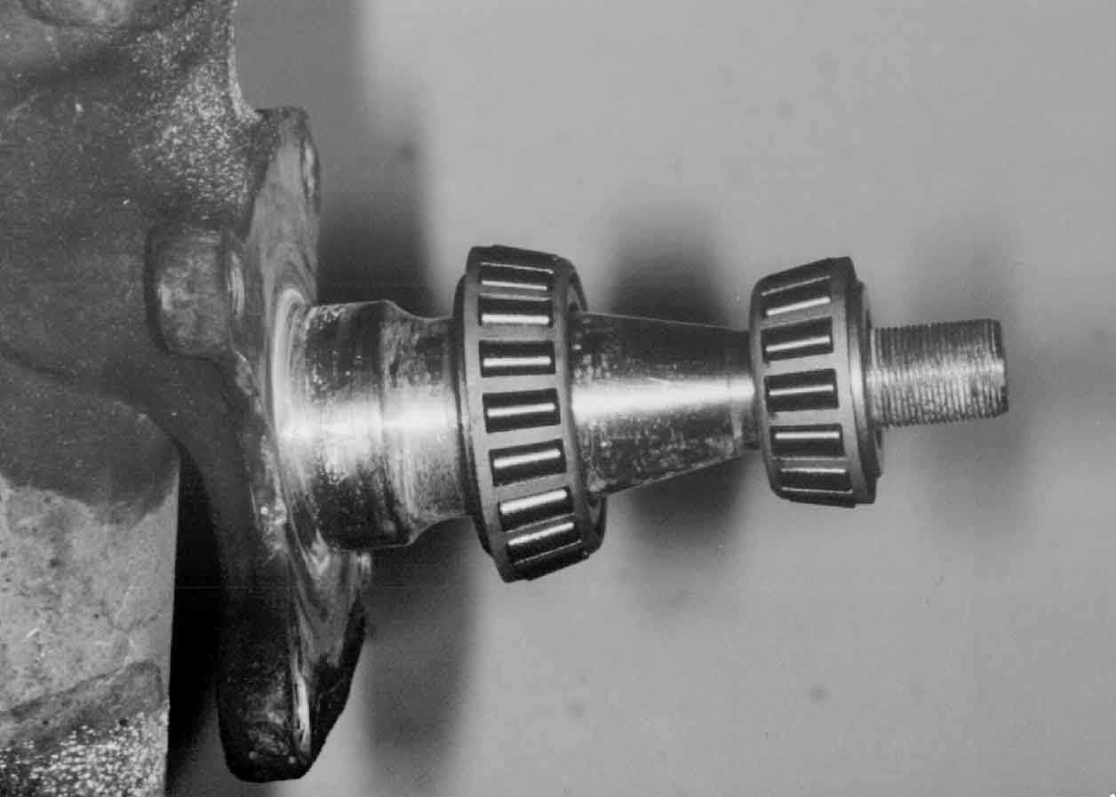
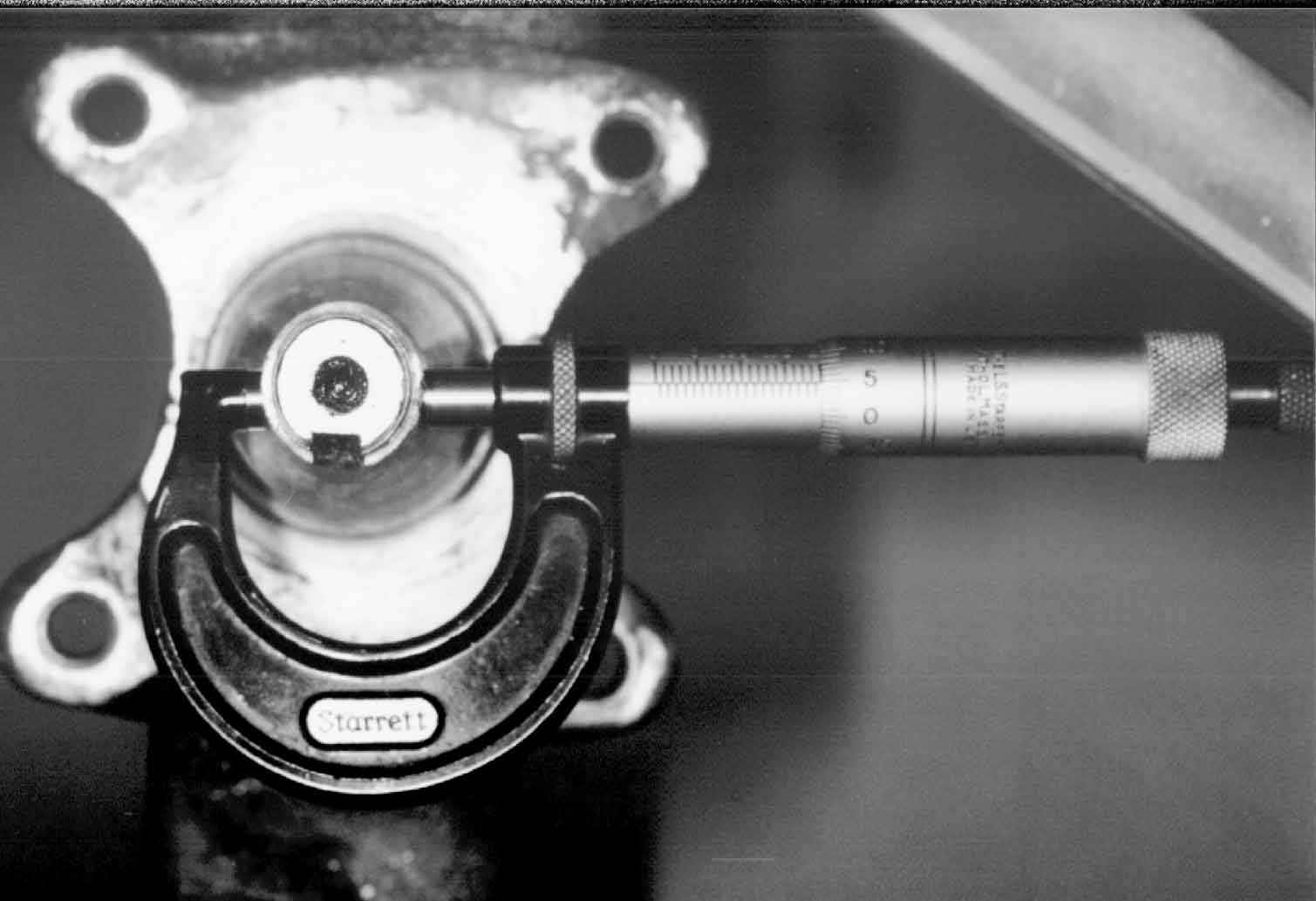
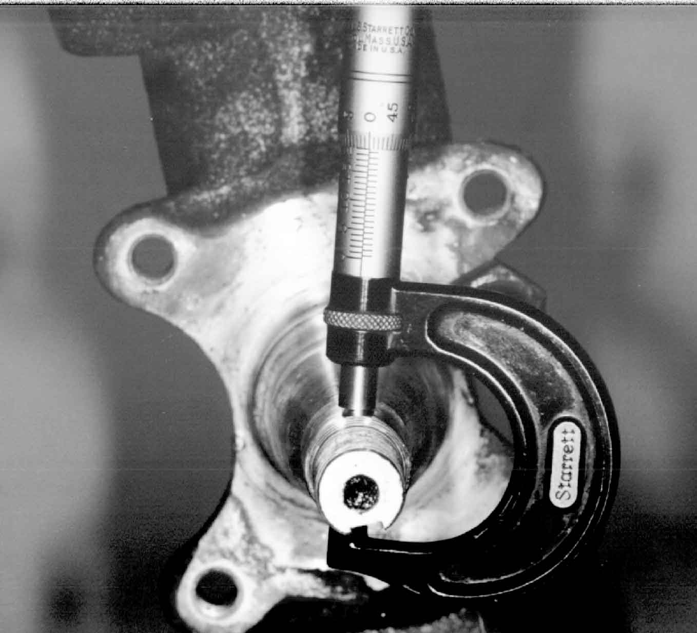
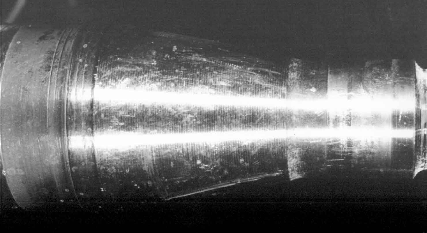
The spindle is a precisely lathed piece of mild steel. It is machined for clearance between the spindle aand the inner races
of the wheel bearings. See Drawing #1. The clearance is from .01mm to .026mm. See also Picture #1.
DRAWING #1
PICTURE #1
Looking at the spindle from the end on view, we have Drawing #2.
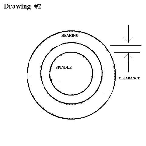
DRAWING #2
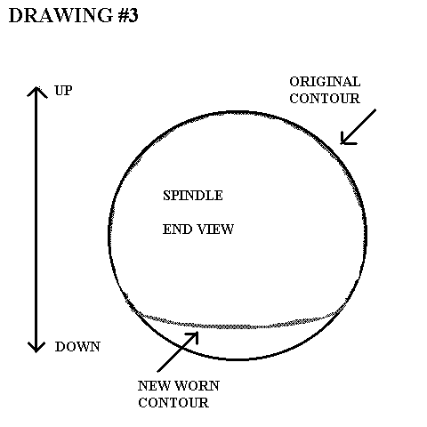
Drawing #2 applies to both bearings (the inner bearing and the outer bearing). However miles of bad roads, or many laps at the track with race tires, or
simply high mileage will hammer the high carbon steel bearing races against the mild steel spindle deforming the
originally round surface into a modified oval. See Drawing #3.
DRAWING #3
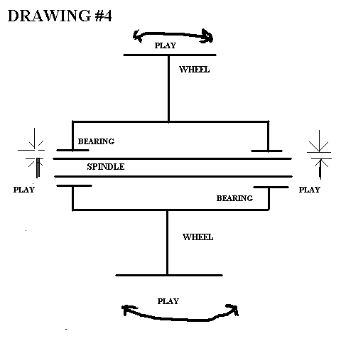
This means there will be more bearing clearance in the verticle axis than in the horizontal axis across the tire. This
translates to a wobble in play in the camber axis. See Pictures #2 and #3. Her e we have .05mm (.002") in ovality on
the outer wheel bearing race surface. PICTURES #2 and #3
PICTURE #2
PICTURE #3
As an example, if we have .002" clearance in each inner race to spindle surface, this will translate to .028" play at the
rim of a 16" wheel. See Drawing #4.
DRAWING #4
This play cannot be adjusted by overtightening the wheel bearing clamping nut. Overtightening this nut will overload the
wheel bearing by applying too much pressure t6o the rollers, and overheat and score them quickly. Overheating will
produce a change in color on the roller surface and scoring will produce circumferential lines around the rollers. This
is dangerous at high speeds because there is a possibility of seizing the bearing and breaking the spindle. The clamping
nut adjustment is designewd to have .001" to .003" play or space between it and the wheel bearing thrust washer.
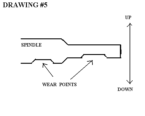
Further, great wear on the spindle from the inner races will produce a step from the worn surface to the original surface
of the spindle. See Drawing #5 and Picture #4 (which is the underside view of the spindle).
DRAWING #5
AND PICTURE #4
This step is a stress riser (a point of concentrated stress). It is an ideal point for the initiation of a developing crack. See
Picture #5 (Picture enhanced for printing). This high mileage and track car spindle was dye checked. A crack has developed
here on the large bearing surface. The risk of breakage is lower on the early cars because of weight, braking, and cornering
forces but increases proportionally to where the hot Turbos would have the smallest safety margin and the highest risk of
breakage with this wheel bearing design.
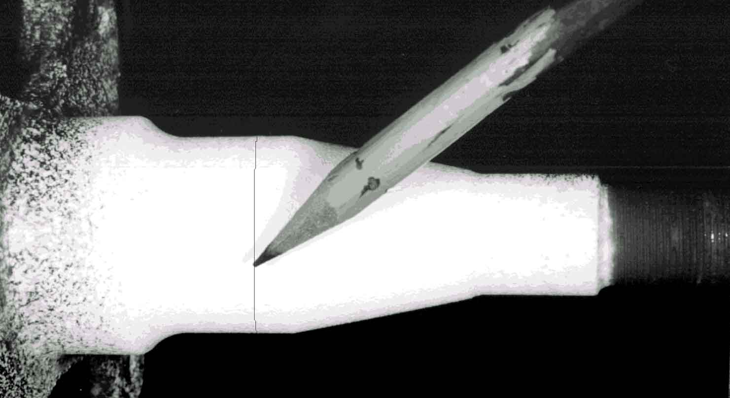
PICTURE #5
In conclusion, high mileage or racing shortens the component life of the car. Careful attention must be paid in
these conditions to maximize the safety and enjoyment of these fine vehicles.