This is a published aticle on repairing the 911 gas tank panel
911 gas tank support panel replacement
By Matt De Maria
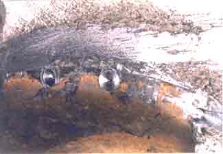
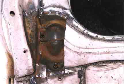
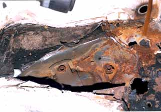
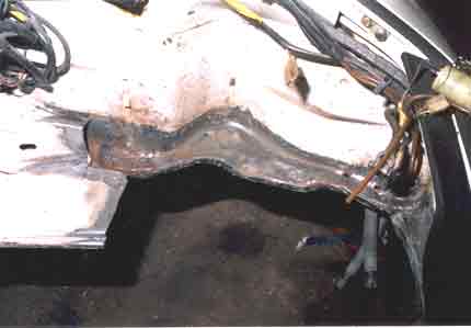
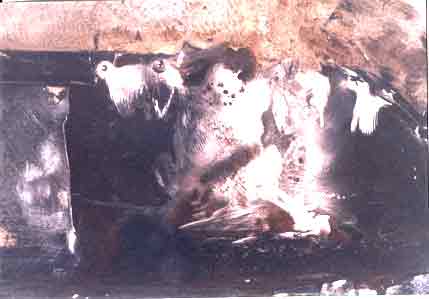
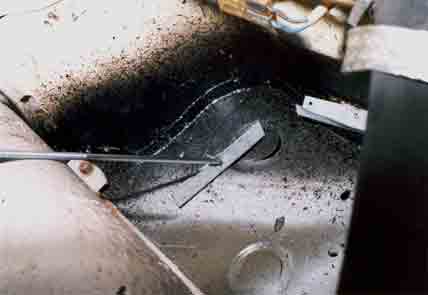
The early 911's (pre-1976) were very susceptible to rust since they did not have any galvanized panels. Thus after 1976, when the 911's were galvanized pan rust was a fairly uncommon occurrence. There were a few cases where battery acid leaked (as a result of a faulty alternator) onto the gas tank support panel corroding the galvanized metal significantly. See Pictures #1, #2, and #3
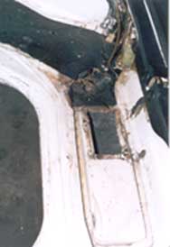
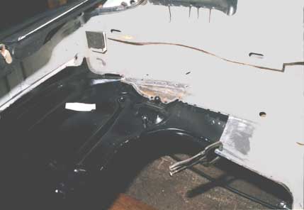
Picture #1
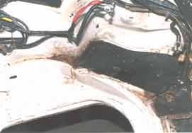
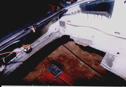
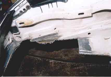
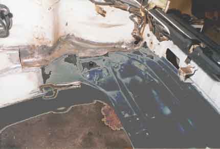
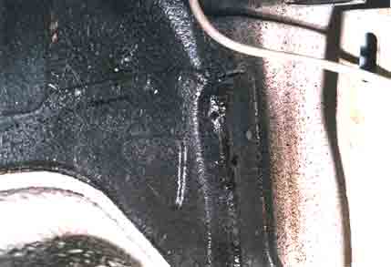
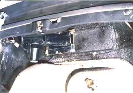
Picture #1 is a view of the front left (battery) side of the trunk. Note the rust under the battery tray and the corrosion to the mount for the condenser fan. Picture #2 shows a closer overhead view of this damage. Also in Picture #3 notice the rust in the frame support at the rear of the battery tray under the battery cables. Picture #4 shows the damage to this support panel after it had been removed from the car.
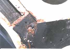
Picture #2
The repair of this panel is not an overly complicated procedure.
It can be performed by anyone having a moderately equipped shop and exercising a lot of patience. Like anything in life the more you put into a project, the more you will get out of it. The majority of the work in these types of projects is the preparation of cleaning the body shutz and removing the old panels carefully. The actual welding takes the least amount of time.
Picture #3
The first task is to clean the body shutz and dirt off of all the pertinent joints and areas. The commonly accepted tools nowadays are special rotating wire brushes that fit onto air die grinder motors. Some of these brushes have the very end of their bristles bent 90 degrees toward the direction of work or rotation. These are fantastic for removing shutz. See Picture #6 for the effect it has in removing the shutz. The next choice are the wire brushes that have their bristles encapsulated by a rubbery compound. The compound is needed as a safety factor since it keeps the bristles from flying off the brush and injuring the user.
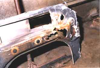
PICTURE #4
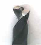
PICTURE #5
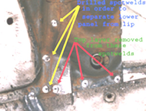
After the joints are cleaned, the next task is to remove the panels by drilling out the spot welds. A spotweld drill bit was used. See Picture #5. This is also a commonly used tool in the industry and this particular size was 8mm in diameter. (They are additionally manufactured in 6mm and 10mm sizes.) By using this bit in a 3/8 drill (around 2000 rpm-important) spotwelds can be removed controllably through the upper panel down to the base metal. See Picture 7A. After the welds are removed, use an air chisel with a sharp bit and pry off the top layer. See Picture #6 for a view of the base panel with top panel removed.
Picture #6
Picture #7
Picture #7A
The next objective is to remove the gas tank support. But the upper battery tray is spotwelded to the gas tank support. In order to save the time of drilling out all of the spotwelds on this upper panel, cuts were made on the left and right side of the upper battery panel in order to gain access to the welds underneath. See Pictures #7 (right side) and #8 (left side). Note the additional corrosion that is revealed under the battery panel (left side).
Picture #8
The front side of the support panel is spotwelded to the body in two rows. The top row is at the upper edge of the support panel and the lower row is at the bottom edge of the front body panel. See Picture #9.
Picture #9
The side edges of the support panel end in a 3/8 lip that is bent 90 degrees to the main surface of the panel. To separate this joint in preparation for removal, an air chisel with a sharp straight bit is used to slice the corner of this 1/4" lip all along the length of this seam on both sides. See the resultant cut on the old panel in Picture #4. (After removal of the old panel, grind down flat the surface of this lip on the body.) See Picture #15.
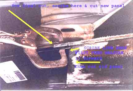
Lateral slices are made on both sides of the old panel. See Pictures #10, #11 and #12. This is accomplished easily by using a "whiz" wheel with a 1/16" thick disc. The method used to find where to cut the old panel is to lay the new panel over the old panel from the bottom of the car. See Picture #13A. (Obviously the trailing arms have to be removed.) Scribe a line at the edge of the new panel onto the bottom of the old panel. Measure back (in the direction of the front bumper) 1" on the bottom of the old panel; this is for a margin of safety so that too much material is not removed. Since a buttweld is ultimately desired here, a flush fit is critical and thus the placement of the final cut is critical.
Picture #10
Picture #11
Picture #12
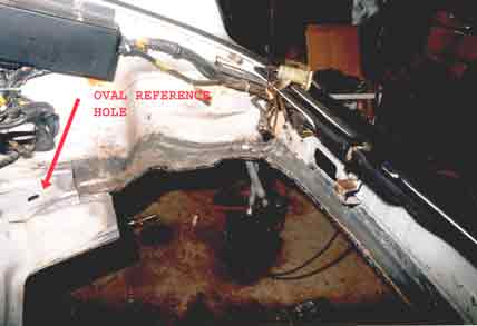
Remove the spotwelds from the right frame strut to the old support panel. Refer back to Picture #10 and #7. On the left side of the car there is an additional problem. The forward part of the left frame strut is rusted. Refer back to photo #3. A vertical cut is made on this old frame strut in order to remove the rusted part and it is also referenced carefully from the oval hole shown in Picture #11.
Careful trimming will allow a nice buttweld to be made here also. See the cut area in Picture #14. The curved part of this left frame support is removed also. See Picture #15. Also refer back to Pictures #11 and #12.
Picture #13
Picture #14
Picture #15
Remove the old support panel and fit the new panel in place. Hold it in place with vice grips. See Pictures #16 and #17. Now the final alignment is performed so the final trimming can be done. The new panel fits laterally with no clearance; so there is no alignment here to worry about. However the longitudinal alignment is critical. According to the factory, the longitudinal distance between the rack mounting bolt (one of the major points of reference on the car) and the rear bolt of the three bolt mount for the front of the front torsion bar bracket is 497.3mm +/- 1mm. The way to measure this is to install the long rack beam bolt in place. Place the end of a tape measure against the forward surface of the bolt as shown in Picture #18 and run the tape measure across the rear outer bolt boss for the front torsion bar mount, as shown in Picture #19. Read the distance to the forward edge of the bolt boss hole. The value in the picture is 496.5mm. Simply loosen the visegrip on this side and move the panel a little forward to obtain the correct value and reclamp. Check and adjust the other side.
Picture #16
Picture #17
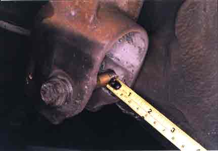
Picture #18
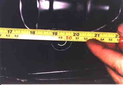
Picture #19
The final trimming is done now. Scribe a line on the top of the new panel using the edge of the body as a reference. See Picture #13B.
Trim the new panel with a "whiz" wheel close and accurately to the line. Clean all surfaces that are to be buttwelded or lapwelded, of all paint and dirt. The metal should be shiny clean. See Picture #15
Next treat all of these cleaned surfaces with a zinc weld-through primer available at most welding shops. This paint protects the surfaces of the lapwelds that face each other once the joint is welded; and it aids the weld by aiding conductivity.
Using a hole puncher (in this case I used a 8mm hole punch) punch holes about every 1 1/4" to 1 1/2" into the flange around the periphery of the new support panel except that portion of the panel that is to be buttwelded.
There are two methods to weld lapped seams (overlapping pieces of metal.):
One is resistance spot welding. This method works best in a manufacturing setting. The panel surfaces have to be new and smooth. The surface finish has to be mirror smooth in order for the resistance to be low and thus for the welding current to be high. This technique is very difficult to use on new panels where a lot of labor time has to be spent stripping the paint off of the panel and ensuring that is has a polished finish afterward.
The other method is plug welding. Plug welding is performed by welding (with a mig welder) through a hole in the upper metal surface (already pre-punched) down to the base metal surface. This technique works well in a non-ideal conditions where some of the surfaces are not completely even or clean.
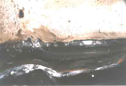
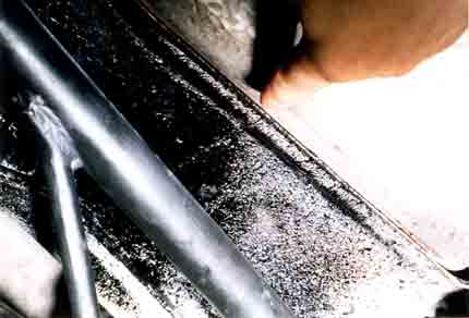
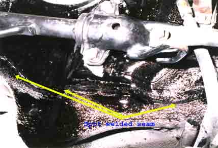
The welding time is fairly small compared to the prep time. Most of the gas tank support panel was spot welded in. The rear part of the panel was buttwelded in. See Pictures #20 and #21 for views of the left and right buttwelds from under the car after the front metal was " shutzed". Also See Pictures #22 and #23 for views of the outer seams of the shutzed support panel from under the car.
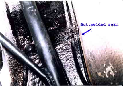
Picture #20
Picture #21
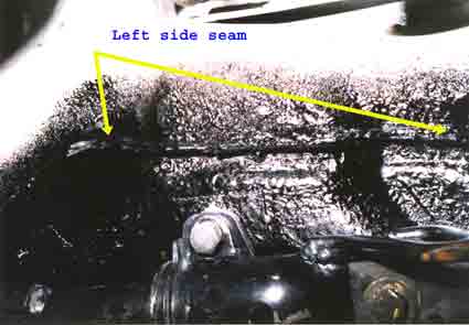
Picture #22
Picture #23
The new left frame strut was fitted into place by measuring the distance from the same oval hole and cutting off the excess. The rear edge of the new panel was buttwelded to the front edge of the old panel and the rest of the panel was spotwelded. See Picture #24 for a view of the left frame strut area. Mounts for an OPTIMA battery are pop-riveted in place here.
Picture #24
Picture #25
The upper battery tray is next in the order of assembly.
Picture #25 shows the right side side upper battery support tray meeting the right frame strut.
After the upper battery tray is welded in, the condenser fan mount is placed on the edge of the tray and then welded.
Picture #26 shows the condenser fan mount welded on top of the upper battery tray. NOTE: The gas tank support (This particular piece came from the aftermarket) was not supplied with the condenser hole. The parts fiche for this year does not show a condenser hole in this panel either. Because of this fact the hole dimensions were carefully transferred from the old panel onto the new panel. The last piece to weld is the end piece for the battery tray. It mounts on top of the frame strut and upper battery support and is spot welded against the front wall of the body.
Picture #26
In summary the replacement of rusted body panels is not rocket science but it is an art honed by experience, care, and logical thought. Some of the experience can be substituted by information from people who have done this type of work. A mig welder is a necessity and some sort of grinder is extremely helpful for cleaning metal. Other tools can be substituted for the ones mentioned in this article.